Multiplexers
Created by Pavly G.
A Multiplexer, or MUX, is a data selector device that routes more than one input line to a single output.
One input can be routed to the output line by using a state of combination of selection lines.
Channels of an MUX are described as follows: 1) Input data lines (Dn). 2) One output data line (Y). 3) Selection lines (A, B, C, …).
The number of selection lines can be calculated by taking the log2(n); where (n) is the number of the input data lines and the logarithmic base (2) corresponds to the 2 unique binary states (0) and (1).
For example, in order to route 8-bits to a single data output, one will need to provide log2(8) = 3 selection lines, likewise the number of selection combinations is the same as the number of the input data lines and can be calculated from the number of the selection lines using 2^3 = 8; where (3) is the number of selection lines, (2) is the base of the exponential function and represents the binary states, and (8) is the number of input data lines that need to be routed.
Here is an example of 8-to-1 MUX and its truth table:
Note: Output (W) is a complementary output channel that inverts the signal produced at output (Y).
The internal logic circuit
The internal logic circuit of a MUX consists mainly of:
1) One AND Logic gate for each input channel.
2) One NOT Logic gate for each selection channel.
3) One final routing OR Logic gate for the MUX that adds those AND Gates.
Here is the logic circuit diagram for a 2-to-1 MUX with its truth table:
And Here is the logic circuit diagram for a 4-to-1 MUX with its truth table:
Note: The selection lines can be thought of as the
index of the input channelto be routed to the output channel from a high-level perspective.For example, here to select (I0) to be routed, the selection bit should be (0) indicating that index (0) input channel should be routed to the output channel (Y), and to select (I1) to be routed, the selection bit should be (1) indicating that index (1) input channel should be routed to the output channel (Y).
Again, the number of selection lines for this circuit can be calculating by taking the log2(2) which gives 1; where base (2) is the number of binary states (0 - 1), and (2) is the number of the input data lines.
The number of the input channels for each utilized AND circuit can be calculated by the following equation:
Number of selection lines + 1 (input data line) + 1 (for ENABLE bit).
The number of the input channels to the routing OR gate equals the number of the input data lines.
Constructing Boolean Functions
-
The first step in constructing a boolean function is to find out its
minterms, a minterm is the expression constructed using the AND logic gates, in this case, an input channel is considered a minterm; because it’s routed into an AND Logic gate. -
The selected minterms should be assigned a state of logic ‘1’, while other minterms (input data lines) should be disabled by assigning them to GND (a state of logic ‘0’).
-
Now, a boolean function is constructed by adding the desired minterms (input data lines).
Example:
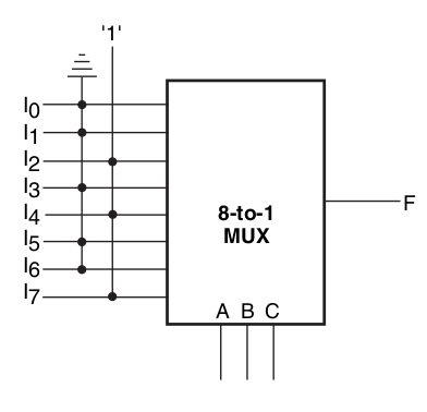
In this logic circuit of a 8-to-1 MUX, D2, D4 and D7 are activated, while other channels
are deactivated giving the following boolean function:
Y = f (A, B, C) = Summation-of (D2, D4, D7) = ~A.B.~C + A.~B.~C + A.B.C

- The ~A.B.~C corresponds to [010] selection code which routes the D2 input data channel.
- The A.~B.~C corresponds to [100] selection code which routes the D4 input data channel.
- The A.B.C corresponds to [111] selection code which routes the D7 input data channel.
Life Applications
Data transmission to large distances can be achieved using MUXs. A MUX can convert Parallel Data lines to Serial single output data line providing that a counter is connected to the selection data lines, the counter clocks out the input data lines serially at the output line by incrementing the selection code.
Encoders and Priority Encoders are constructed mainly from MUX devices by removing the single output line and adding (n) output lines, in which (n) corresponds to the number of selection lines of the MUX.
Encoders are covered in a separate post.
Cascading MUX
A 8-to-1 MUX can be cascaded into 16-to-1 MUX or 32-to-1 MUX and so on…
To calculate the number of the available MUX to build the desired MUX, this equation should be used:
2^(N-n); where (N) is the number of the selection lines of the desired MUX and (n) is the number of the selection lines of the available MUX.
To calculate the number of the selection lines of those MUXs, take the log2(n); where n is the number of the input channels.
Connecting a MUX cascading circuit requires connecting selection lines of the available MUX devices, an additional selection line should be constructed and connected to the ENABLE bits of both MUXs, such that, assigning (0) to this line will select the least significant MUX device and assigning (1) will select the most significant MUX device, this construction requires a NOT-Gate at the most significant MUX in case of using active low ENABLE MUX.
Here is an example of the logic circuit: